Difference between revisions of "DI Electronics Workshop"
From Wikicliki
| Line 1: | Line 1: | ||
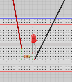
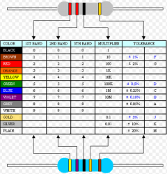
| − | [[File:circuit1.png]] | + | [[File:circuit1.png]] [[File:resistors.png|240px]] |
* LED - small side = long leg = positive | * LED - small side = long leg = positive | ||
* Connectors - red wires positive / black wires negative or ground (why GND? GND = grounding for discharge) | * Connectors - red wires positive / black wires negative or ground (why GND? GND = grounding for discharge) | ||
* Resistor - if you didn't have it the LED would blow / it makes sure the led does not draw all of the 5v current / 220 Ohms Resistor - red red brown is 22 *10 | * Resistor - if you didn't have it the LED would blow / it makes sure the led does not draw all of the 5v current / 220 Ohms Resistor - red red brown is 22 *10 | ||
| − | * Resistance is calculated in ohms. So how do we figure out the current? | + | * Resistance is calculated in ohms. So how do we figure out the current? The Lab power supply has a switch for amps/volts you can see its about 0.01. |
| − | |||
Revision as of 11:38, 28 October 2013
- LED - small side = long leg = positive
- Connectors - red wires positive / black wires negative or ground (why GND? GND = grounding for discharge)
- Resistor - if you didn't have it the LED would blow / it makes sure the led does not draw all of the 5v current / 220 Ohms Resistor - red red brown is 22 *10
- Resistance is calculated in ohms. So how do we figure out the current? The Lab power supply has a switch for amps/volts you can see its about 0.01.

