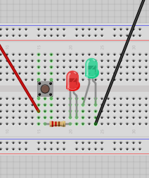
Basic Circuits
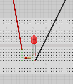
- LED - small side = long leg = positive
- Connectors - red wires positive / black wires negative or ground (why GND? GND = grounding for discharge)
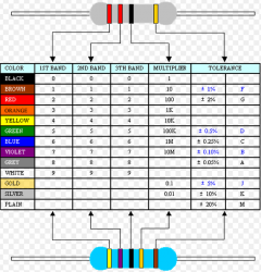
- Resistor - if you didn't have it the LED would blow / it makes sure the led does not draw all of the 5v current / 220 Ohms Resistor - red red brown is 22 *10
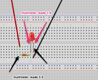
- Resistance is calculated in ohms. So how do we figure out the current? The Lab power supply has a switch for amps/volts you can see its about 0.01.
- V=IR: See more about Ohm's Law
- Using Multimeter: solid line dc, wavy line ac, turn to 20
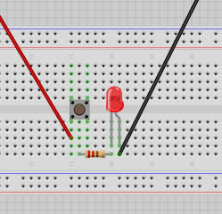
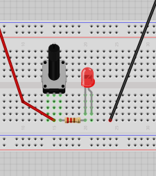
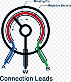
- Variable Resistor: aka Rotary Potentometer [use middle pin and side pin]
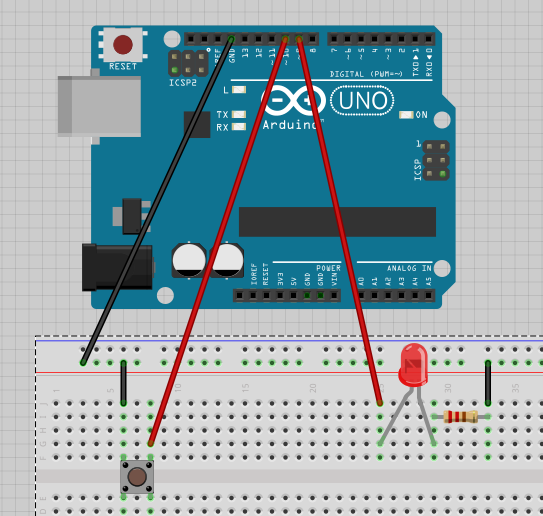
Arduino
- the big brick is the microcontroller
- spk16000 - oscilator - crystal
- push up and push down resistor - if you put it before or after the led - but it works like a kind of pipe anyway it seems, if the pipe is smaller then less will flow overall...
 |
int yellowled = 9;
int myButton = 10;
int buttonVal = 0;

void setup(){
  pinMode(myButton, INPUT_PULLUP);
  pinMode(yellowled, OUTPUT);
}
void loop(){
  buttonVal = digitalRead(myButton);
  if (buttonVal == HIGH) {
    digitalWrite(yellowled, HIGH);
  }
  else {
    digitalWrite(yellowled, LOW);
  }
}
//fade in and out when clicked
  buttonVal = digitalRead(myButton);
    analogWrite(yellowled, brightness);
    if (buttonVal == LOW){
          int newAngle = potValue;
          if (brightness < 255){
          brightness = brightness + fadeAmount;
          }
    }
    if (buttonVal == HIGH){
        int newAngle = 90;
          if (brightness > 0){
          brightness = brightness - fadeAmount;
          }
    }
|
|
#include <Servo.h>
int potValue = 0;
int potPin = A0;
int servoPin = 8;
int servoAngle;

Servo myServo;

void setup() {
  Serial.begin(9600); //SERIAL MONITOR
  potValue = 0;
  myServo.attach(servoPin); //servoAngle
}

void loop() {
  potValue = analogRead(potPin);
  Serial.println(servoAngle);

  servoAngle=map(potValue,0,1023,0,180); // ummappen auf degrees
  servoAngle=constrain(servoAngle, 0, 180); // defensive coding
  myServo.write(servoAngle);
}
|
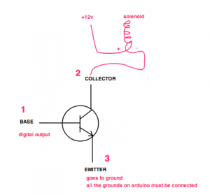
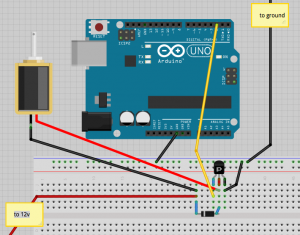
Solenoids / Transistors
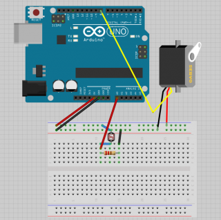
- solenoid - 12v - bigger than what your usb 5v can provide - you need to use transistors instead for higher loads
- solenoid: "In physics, the term refers specifically to a long, thin loop of wire, often wrapped around a metallic core, which produces a uniform magnetic field in a volume of space (where some experiment might be carried out) when an electric current is passed through it. Solenoids are important because they can create controlled magnetic fields and can be used as electromagnets."
- 'solenoid" (simplified): a cylindrical coil of wire acting as a magnet when carrying electric current.
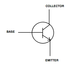
Darlington Transistor
- A darlington is two transistors - consisting of two bipolar transistors (either integrated or separated devices) connected in such a way that the current amplified by the first transistor is amplified further by the second one.
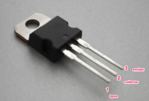
Mosfet Transistor
- The metal–oxide–semiconductor field-effect transistor (MOSFET, MOS-FET, or MOS FET) is a transistor used for amplifying or switching electronic signals.
- Good for doing high loads
- IRF630 - if you google it you get the data sheet - IRF630 Datasheet
- Non stripe side of diode connects next to transistor
- The Diode used is a N4001
- VIn Pin on your Arduino - if you put 12v into arduino and ground it you will power arduino on its own - you just need a 12v power supply. but you need enough amperes.
 | //default blink sketch, just check which pin you connected to
int led = 2;
void setup() {
pinMode(led, OUTPUT);
}
void loop() {
digitalWrite(led, HIGH); // turn the LED on (HIGH is the voltage level)
delay(1000); // wait for a second
digitalWrite(led, LOW); // turn the LED off by making the voltage LOW
delay(1000); // wait for a second
} |
 | //default blink sketch, just check which pin you connected to
int led = 2;
void setup() {
pinMode(led, OUTPUT);
}
void loop() {
digitalWrite(led, HIGH); //
} |
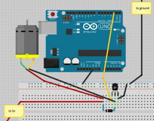
Motor
/* Example - Motor slows down gradually */
int motorPin = 11; // remember to pick a pin with the squiggly line
// only pins with squiggly line can do fading/dimming
void setup(){
	pinMode(11,OUTPUT);
}
void loop(){
	analogWrite(11,255);
	delay(300);
	analogWrite(11,200);
	delay(300);
	analogWrite(11,150);
	delay(300);
	analogWrite(11,100);
	delay(300);
	analogWrite(11,50);
	delay(300);
	analogWrite(11,20);
	delay(300);
}
|
/* Variation of making it spin at different spins */
int motorPin = 11;
int motorSpeed = 255;
int speedRate = 50;

void setup(){
	pinMode(motorPin,OUTPUT);
}

void loop(){
	analogWrite(motorPin,motorSpeed);
        motorSpeed = motorSpeed + speedRate;
        if (motorSpeed == 0 || motorSpeed == 255) {
        speedRate = -speedRate ;
        }
        delay(30);
}
|
Integrated Circuits
- H Bridge - An H bridge is an electronic circuit that enables a voltage to be applied across a load in either direction. These circuits are often used in robotics and other applications to allow DC motors to run forwards and backwards.
- Integrated Circuits or ICs are fragile. They will burn easily. You can even burn them through static electricity.
- L293D IC (H Bridge) - Count from the notch clockwise left is 1, 2, 3… etc. See diagram here: http://luckylarry.co.uk/arduino-projects/control-a-dc-motor-with-arduino-and-l293d-chip/
- H Bridges are useful for robots that roll around.
- Why are there four grounds? because the manufacturer chose a chip that size (it is a standard type thing) and there were extra pins
- Why is it called L293DNE on my chip? They should in theory be the same, just made by different manufacturers. L293D is made by ST and L293DNE is made by Toshiba
- Is your H Bridge not working? PRESS IT IN HARDER. It needs to really snap in.
 |
int enable = 11;
int input1 = 10;
int input2 = 9;

void setup(){
pinMode(enable, OUTPUT);
pinMode(input1, OUTPUT);
pinMode(input2, OUTPUT);
}

void loop(){

	//set direction of motor
	digitalWrite(input1, HIGH);
	digitalWrite(input2, LOW);

	//turn on motor
	digitalWrite(enable, HIGH);
	delay(2000);

	//turn off motor
	digitalWrite(enable, LOW);
	delay(2000);

        // CHANGE DIRECTION
	//set direction of motor
	digitalWrite(input1, LOW);
	digitalWrite(input2, HIGH);

	//turn on motor
	digitalWrite(enable, HIGH);
	delay(2000);

	//turn off motor
	digitalWrite(enable, LOW);
	delay(2000);

	// slow down motor
	analogWrite(enable, 50);
	delay(2000);

	//turn off motor
	digitalWrite(enable, LOW);
	delay(2000);
} |
/* class explanation of how functions work */
int enable = 11;
int input1 = 10;
int input2 = 9;

void setup(){
pinMode(enable, OUTPUT);
pinMode(input1, OUTPUT);
pinMode(input2, OUTPUT);
}

void motorClockwise(){
  	digitalWrite(input1, HIGH);
	digitalWrite(input2, LOW);
}

void motorAntiClockwise(){
  	digitalWrite(input1, LOW);
	digitalWrite(input2, HIGH);
}

void motorTurnOn(){
        digitalWrite(enable, HIGH);
}

void motorTurnOff(){
        digitalWrite(enable, LOW);
}

void setSpeedofMotor(int s){
  analogWrite(enable, s)
}

void loop(){
  motorClockwise();
  delay(2000);
  motorTurnOff();
  delay(2000);
  motorTurnOn();
  delay(2000);
  motorAntiClockwise();
  delay(2000);
  setSpeedofMotor(50);
  delay(2000);
}
|
Other Parts Yet to be introduced
- ball switch
- relay
- temperature sensor
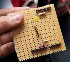
PCB
- strip board, perf board - copper and fibreglass
- etching powder
- Suggestion - integrate with Arduino Mini
Printing your own circuit board
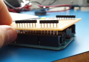
Strip Board
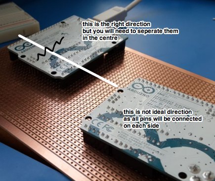 | 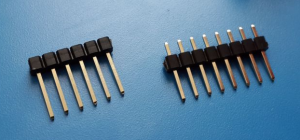
Push the pins to one end so it can sit on top of the stripboard over the arduino
 |
|  |
| int led = 2;
int ldr = A0; //analog pin to which LDR is connected
int ldr_value = 0; //variable to store LDR values
int sound_value = 220;
int threshold - 140;
void setup() {
pinMode(led, OUTPUT);
Serial.begin(9600);
}
void loop() {
ldr_value = analogRead(ldr);
Serial.println(ldr_value);
digitalWrite(led, HIGH);
if (ldr_value <= threshold) {
tone(3, sound_value);
}
} |
Troubleshooting Soldering Issues
- Check if any pins are loose, if they are, resolder
- Check if any two solders are touching even if very little, if so, desolder and fix
- Check if any parts you stripped off were not totally stripped off, even if very very little. If you are the kind to overdo the stripping, you can try to make the strip in a zig-zag function (alternate rows) so that it won't break
- Shortcircuit/mac kernel panic/usb drawing too much power? - check ALL of the above
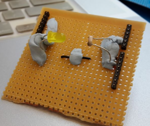
Capacitive Sensor
Resistors
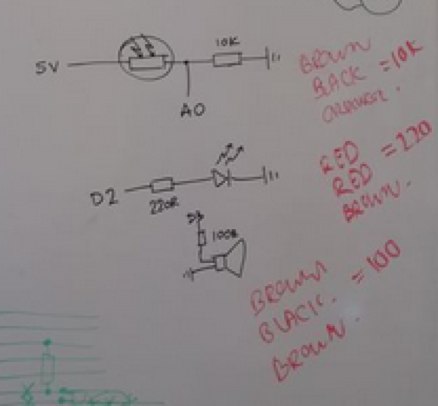
See Chart here - Resistors
- Brown black orange = 10k
- Red Red brown = 220
- Brown black brown = 100
Thoughts/Questions
- IOIO is an android/bluetooth module. Why should one use that over a wifi shield with xively?
- How do I run pure data?
- what are solenoids used in? pistons?
inspiration
shops
Trivia & other interesting things
- Oscilloscope and Decoupling
- UK Mains has a 50Hz hum. Depending on where or what time (eg: when eastenders ends and everyone puts on the kettle) this hum will change. It is alleged that you can find out what time or location it is from the hum - mains hum signature. From wikipedia: "Electrical network frequency (ENF) analysis is a forensic technique for validating audio recordings by comparing frequency changes in background mains hum in the recording with long-term high-precision historical records of mains frequency changes from a database. In effect the mains hum signal is treated as a time-dependent digital watermark that can be used to find when the recording was created, and to help to detect any edits in the sound recording"
- IOIO: https://www.sparkfun.com/tutorials/280
- Circuits.io: http://www.circuits.io/circuits/new
- Fritzing: http://fritzing.org/download/ [All the above diagrams were from Fritzing]


