Difference between revisions of "DI Electronics Workshop"
From Wikicliki
(→Mosfet Transistor) |
|||
| Line 76: | Line 76: | ||
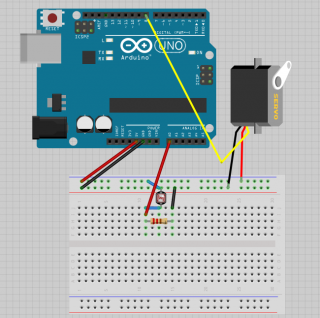
servoAngle=map(potValue,0,1023,0,180); // ummappen auf degrees | servoAngle=map(potValue,0,1023,0,180); // ummappen auf degrees | ||
| − | servoAngle=constrain(servoAngle, 0, 180); // defensive coding | + | servoAngle=constrain(servoAngle, 0, 180); // defensive coding |
myServo.write(servoAngle); | myServo.write(servoAngle); | ||
}</pre> | }</pre> | ||
Revision as of 12:17, 29 October 2013
Contents
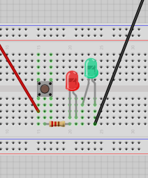
Basic Circuits
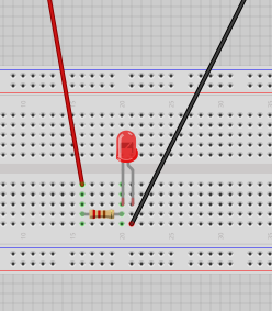
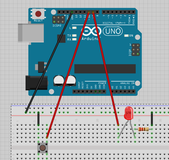
- LED - small side = long leg = positive
- Connectors - red wires positive / black wires negative or ground (why GND? GND = grounding for discharge)
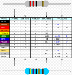
- Resistor - if you didn't have it the LED would blow / it makes sure the led does not draw all of the 5v current / 220 Ohms Resistor - red red brown is 22 *10
- Resistance is calculated in ohms. So how do we figure out the current? The Lab power supply has a switch for amps/volts you can see its about 0.01.
- V=IR: See more about Ohm's Law
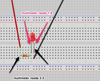
- Using Multimeter: solid line dc, wavy line ac, turn to 20
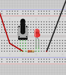
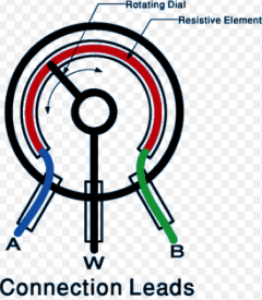
- Variable Resistor: aka Rotary Potentometer [use middle pin and side pin]
Arduino
- the big brick is the microcontroller
- spk16000 - oscilator - crystal
- push up and push down resistor - if you put it before or after the led - but it works like a kind of pipe anyway it seems, if the pipe is smaller then less will flow overall...
Solenoids / Transistors
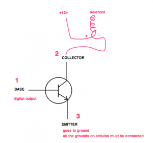
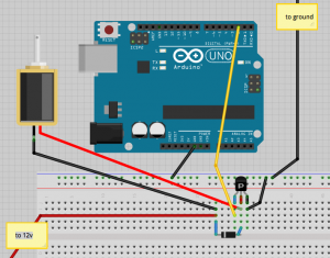
- solenoid - 12v - bigger than what your usb 5v can provide - you need to use transistors instead for higher loads
- solenoid: "In physics, the term refers specifically to a long, thin loop of wire, often wrapped around a metallic core, which produces a uniform magnetic field in a volume of space (where some experiment might be carried out) when an electric current is passed through it. Solenoids are important because they can create controlled magnetic fields and can be used as electromagnets."
Darlington Transistor
- A darlington is two transistors - consisting of two bipolar transistors (either integrated or separated devices) connected in such a way that the current amplified by the first transistor is amplified further by the second one.
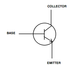
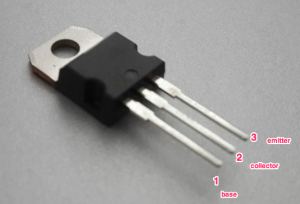
Mosfet Transistor
- The metal–oxide–semiconductor field-effect transistor (MOSFET, MOS-FET, or MOS FET) is a transistor used for amplifying or switching electronic signals.
- Good for doing high loads
- IRF630 - if you google it you get the data sheet - IRF630 Datasheet
- Non stripe side of diode connects next to transistor
- VIn Pin on your Arduino - if you put 12v into arduino and ground it you will power arduino on its own - you just need a 12v power supply. but you need enough amperes.
Thoughts/Questions
- IOIO is an android/bluetooth module. Why should one use that over a wifi shield with xively?
- How do I run pure data?
Trivia & other interesting things
- UK Mains has a 50Hz hum. Depending on where or what time (eg: when eastenders ends and everyone puts on the kettle) this hum will change. It is alleged that you can find out what time or location it is from the hum - mains hum signature. From wikipedia: "Electrical network frequency (ENF) analysis is a forensic technique for validating audio recordings by comparing frequency changes in background mains hum in the recording with long-term high-precision historical records of mains frequency changes from a database. In effect the mains hum signal is treated as a time-dependent digital watermark that can be used to find when the recording was created, and to help to detect any edits in the sound recording"
- IOIO: https://www.sparkfun.com/tutorials/280
- Circuits.io: http://www.circuits.io/circuits/new
