DI Electronics Workshop
From Wikicliki
Basic Circuits
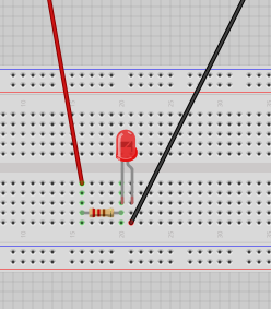
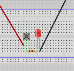
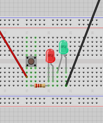
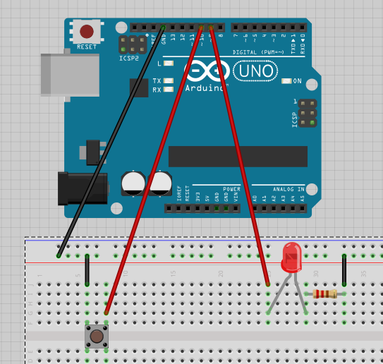
- LED - small side = long leg = positive
- Connectors - red wires positive / black wires negative or ground (why GND? GND = grounding for discharge)
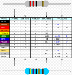
- Resistor - if you didn't have it the LED would blow / it makes sure the led does not draw all of the 5v current / 220 Ohms Resistor - red red brown is 22 *10
- Resistance is calculated in ohms. So how do we figure out the current? The Lab power supply has a switch for amps/volts you can see its about 0.01.
- V=IR: See more about Ohm's Law
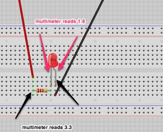
- Using Multimeter: solid line dc, wavy line ac, turn to 20
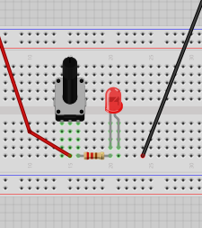
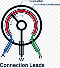
- Variable Resistor: aka Rotary Potentometer [use middle pin and side pin]
Arduino
- the big brick is the microcontroller
- spk16000 - oscilator - crystal
- push up and push down resistor - if you put it before or after the led - but it works like a kind of pipe anyway it seems, if the pipe is smaller then less will flow overall...
Thoughts/Questions
- IOIO is an android/bluetooth module. Why should one use that over a wifi shield with xively?
- How do I run pure data?
Trivia & other interesting things
- UK Mains has a 50Hz hum. Depending on where or what time (eg: when eastenders ends and everyone puts on the kettle) this hum will change. It is alleged that you can find out what time or location it is from the hum - mains hum signature. From wikipedia: "Electrical network frequency (ENF) analysis is a forensic technique for validating audio recordings by comparing frequency changes in background mains hum in the recording with long-term high-precision historical records of mains frequency changes from a database. In effect the mains hum signal is treated as a time-dependent digital watermark that can be used to find when the recording was created, and to help to detect any edits in the sound recording"
- IOIO: https://www.sparkfun.com/tutorials/280
- Circuits.io: http://www.circuits.io/circuits/new
