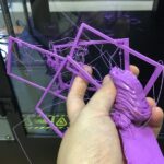
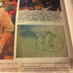
This week I’ve been teaching myself how to use OpenSCAD, a free software which allows one to create 3D CAD models through programming. The syntax is really simple, logical, and surprisingly quick to experiment with – although if you would imagine there is an aesthetic trade-off between producing something super quick to model, render, and print – by default the simple primitives are of a low-poly quality, because this will suffice for most people producing functional household fixes. I find it interesting that by default the aesthetic of most objects printed from OpenSCAD will then automatically have the ‘computer aided design’ look.
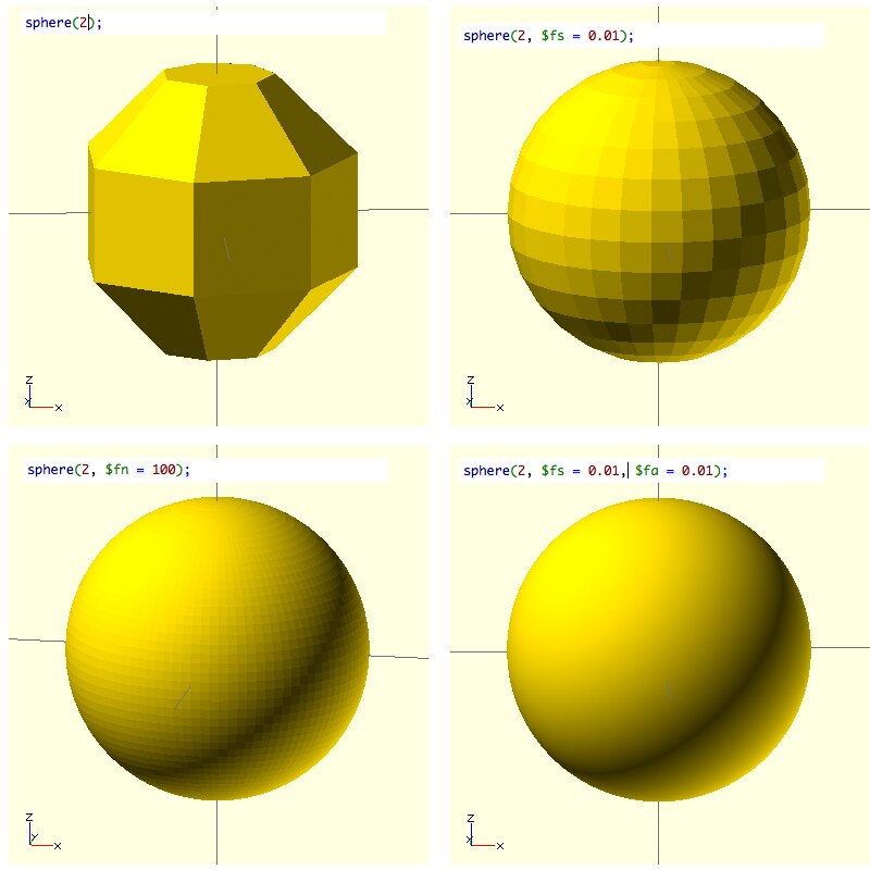
To understand what I mean, here is an example of the same sphere with different overrides. There are actually special variables which can be bumped down to improve the quality = which control the number of facets used to generate all the arcs:
$fa – minimum angle for fragment (min value is 0.01)
$fs – minimum size of a fragment (min value is 0.01)
$fn – number of facets (this overrides the other two when present)
Two other functions for rounding off things are hull() (which effectively gloops things together) and minkowski() (which does a Minkowski sum of two point sets.
Hull produces a convex hull of the objects you put together. Think of it as filling all the concave valleys between objects with a big flat hard-edged squeegee and polyfill.
Minkowski sum is touted as an ‘elegant’ way of producing rounded corners, if you apparently overlap objects together such as a cylinder and a cube, but its more complex than just that. The Minkowski sum as I understand it can be used to produce the solid sweep of an object in motion. It can also be used to calculate the set of all the possible positions of an object moving within a space. So in terms of it being used in motion planning, if there is an object which needs to find its way around obstacles in a space, the possible space in which an object can move is the minkowski sum of the obstacles + the object itself at origin rotated 180 deg.
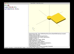
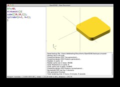
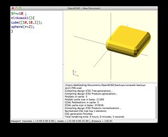
It is indeed a funny, fast way of getting a rounded edge but also potentially CPU intensive as I discovered I needed to drop the number of facets in order to have it process at a reasonable speed. If you use a sphere like in the 3rd example here and change $fn to 30 it may take over 2 hours to compile. So obviously for prototyping you would want to lower the number of facets so you can compile it faster along the way.
Basics transformations:
resize([x, y, z]) { … };
rotate([x, y, z]) { … };
translate([x, y, z]) { … }
mirror( [x, y, z] ) { … }
minkowski() { … }
hull() { … }
Using OpenSCAD to model functional household mods
OpenSCAD is perfect for producing simple household fixes in CAD. Here is an example of a Vileda mop head clothes pole adaptor which I made to hoist up clothing to a curtain rail. I used a vernier caliper to measure the pole and produced a few iterations to find the precise fit/size; the final print is meant to “snap” into place into the Vileda pole.
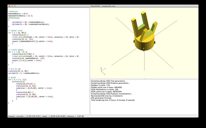
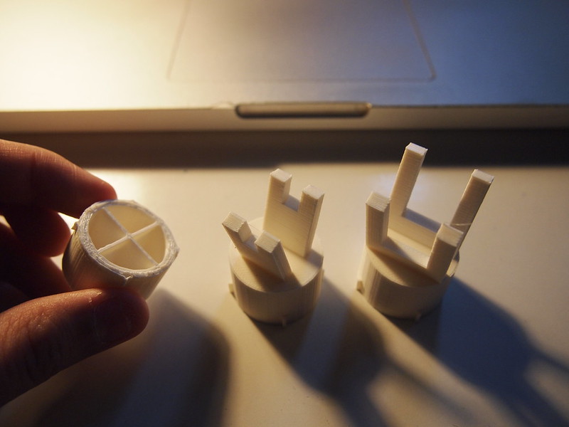
(1) i realised i shouldn’t have printed it on a raft, it does not need to be printed with any support/brim/raft really; (2) i made the prongs too small; (3) prongs are the right size now, but in an attempt to make it fit better, i reduced the bottom by 0.5mm but that was too much…
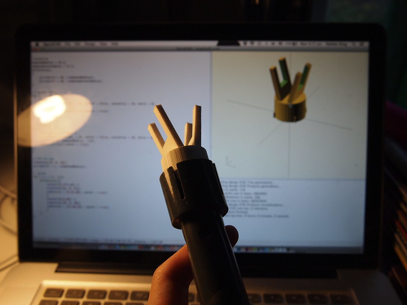
Functional household mod – ACHIEVEMENT UNLOCKED?
Lithophanes
I wanted to understand what might be a good way to produce a lithophane or in OpenSCAD. There was a function “surface” which could use a heightmap (image in dat format). Not surprisingly this is already well-trodden territory but I didn’t want to just use the thingiverse customiser to produce it without understanding it first, so here is my understanding of how it can be produced in OpenSCAD (following the method used in iamwil’s embossanova library)
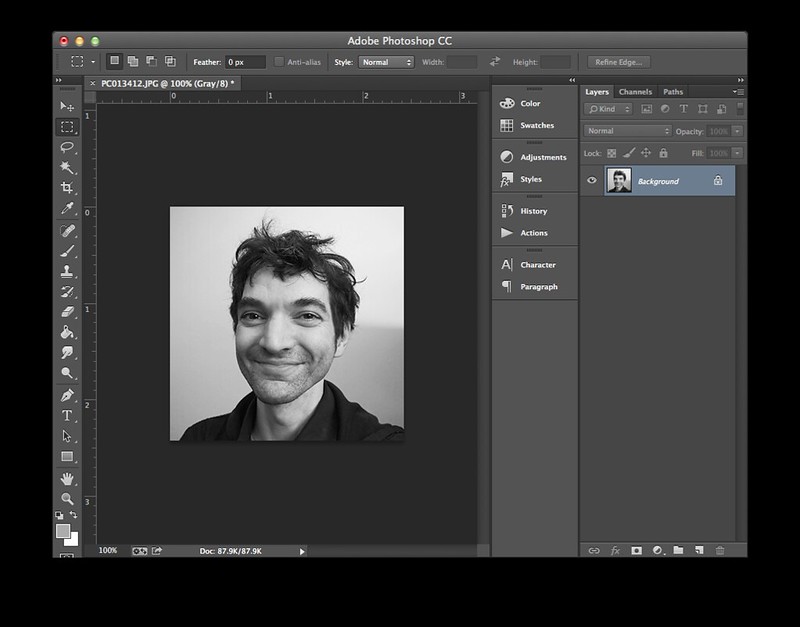
- Started with a fetching image of George which I made into a PNG
- Install Xcode
- Install homebrew
- Install Imagemagick (in terminal > brew install imagemagick)
- Use Imagemagick to convert your image to raw grayscale (eg: in terminal > convert george_gray.png -type Grayscale -negate -depth 8 gray:george_gray.raw)
- Use ruby to convert your raw file into a dat file (i used iamwil’s raw2dat example)
# raw2dat.rb from http://blog.cubehero.com/2013/11/25/emboss-and-impress-images-onto-a-surface-in-openscad/
width = 300 # => width of resized raw image
str = File.binread('george_gray.raw')
pixels = str.unpack("C*")
File.open(‘george_gray.dat’, ‘w’) do |f|
pixels.each_with_index do |pixel, idx|
f.write(pixel)
if ((idx + 1) % width) == 0
f.write(“n”)
else
f.write(” “)
end
end
f.write(“n”)
end
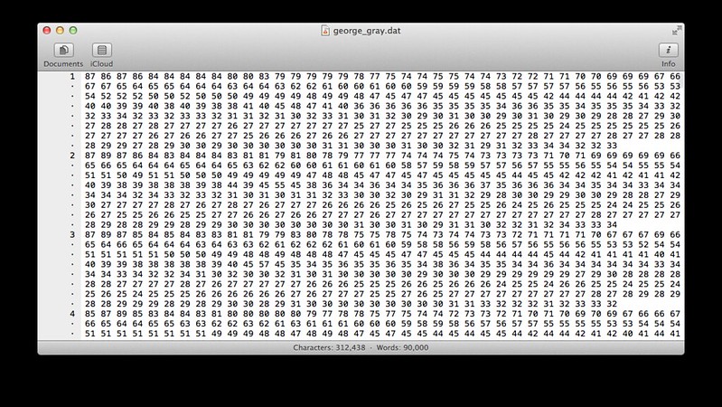
Every pixel in this image is then turned into a number representing the pixel’s grayscale colour. So for an image of 100×100, there will be 100 numbers in each row, and 100 rows. It therefore forms a sort of terrain or heightmap that we can use in OpenSCAD.
mirror([0,1.0]){
scale([1, 1, 1/100])
surface(file = "george_gray.dat", center = true, invert = true, convexity = 5);
}
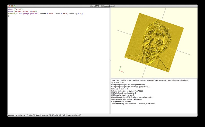
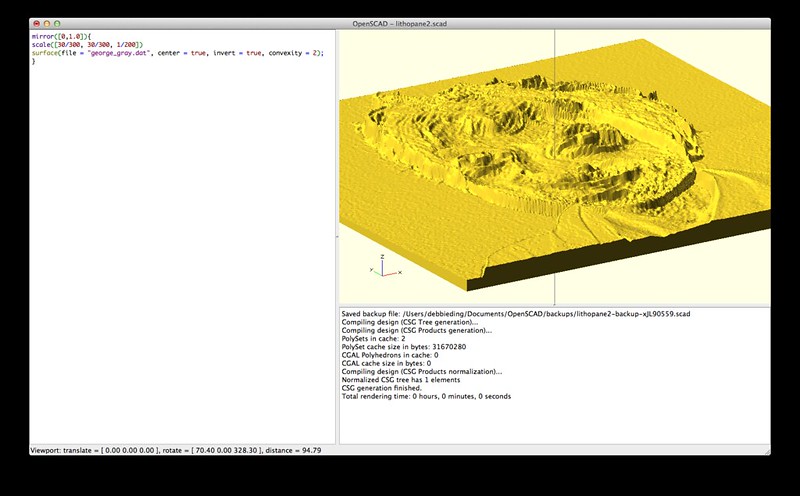
In summary… this seems like an interesting or easy way to generate 3d printed terrains. I imagine you could put in a terrain or topo map for some place and print a 3d terrain out of it. The only problem is that we don’t recognise terrain, so some of its visual impact is lost; whilst George’s face is recognisable from afar and interesting to use (human faces in particular), a naturalistic terrain map is not going to be recognisable or understood in the same way. I’d imagine the only fun part in printing a 3d terrain would be the punctum of confronting someone with a 3d printed model and screaming at them THIS IS THE SURFACE OF THE MOON, NOW IMAGINE YOURSELF AS AN INCONSEQUENTIALLY TINY 0.01MM DUST MITE LIVING ON THIS SLICE OF THE MOON!
PS: the above lithophane of George’s face obviously has too many facets and will take a bazillion boring years to render. So please posterise the faces of your loved ones before turning them into lithophanes.
